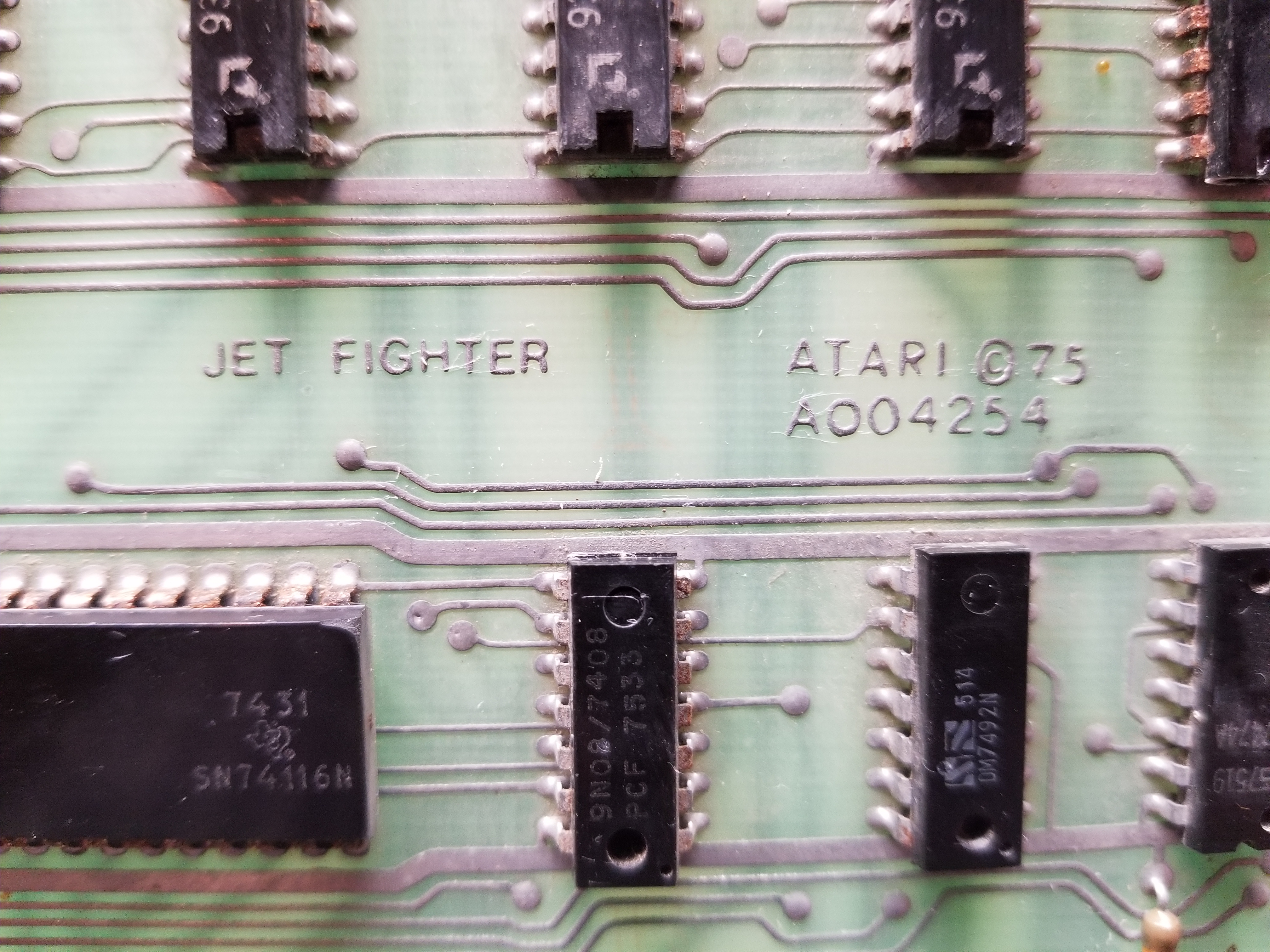
Fixing Atari's Jet Fighter (1975)
.jpg)
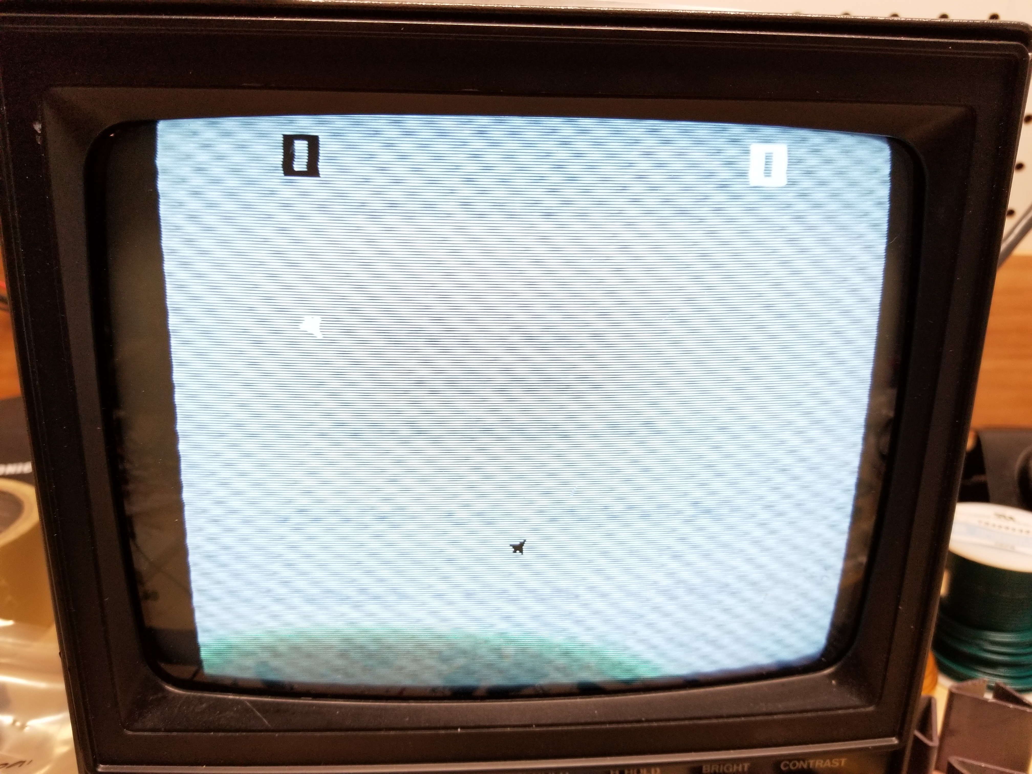
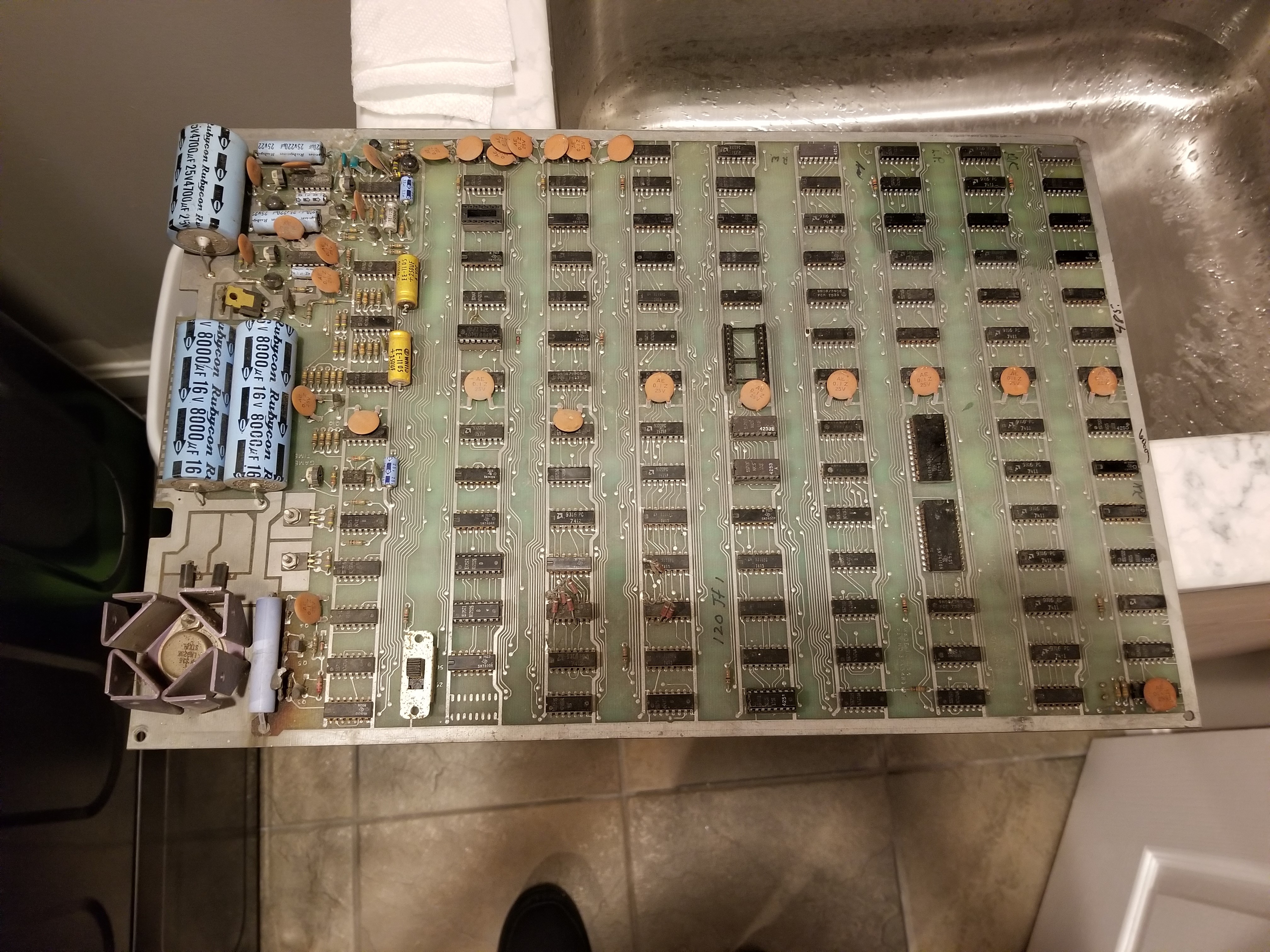
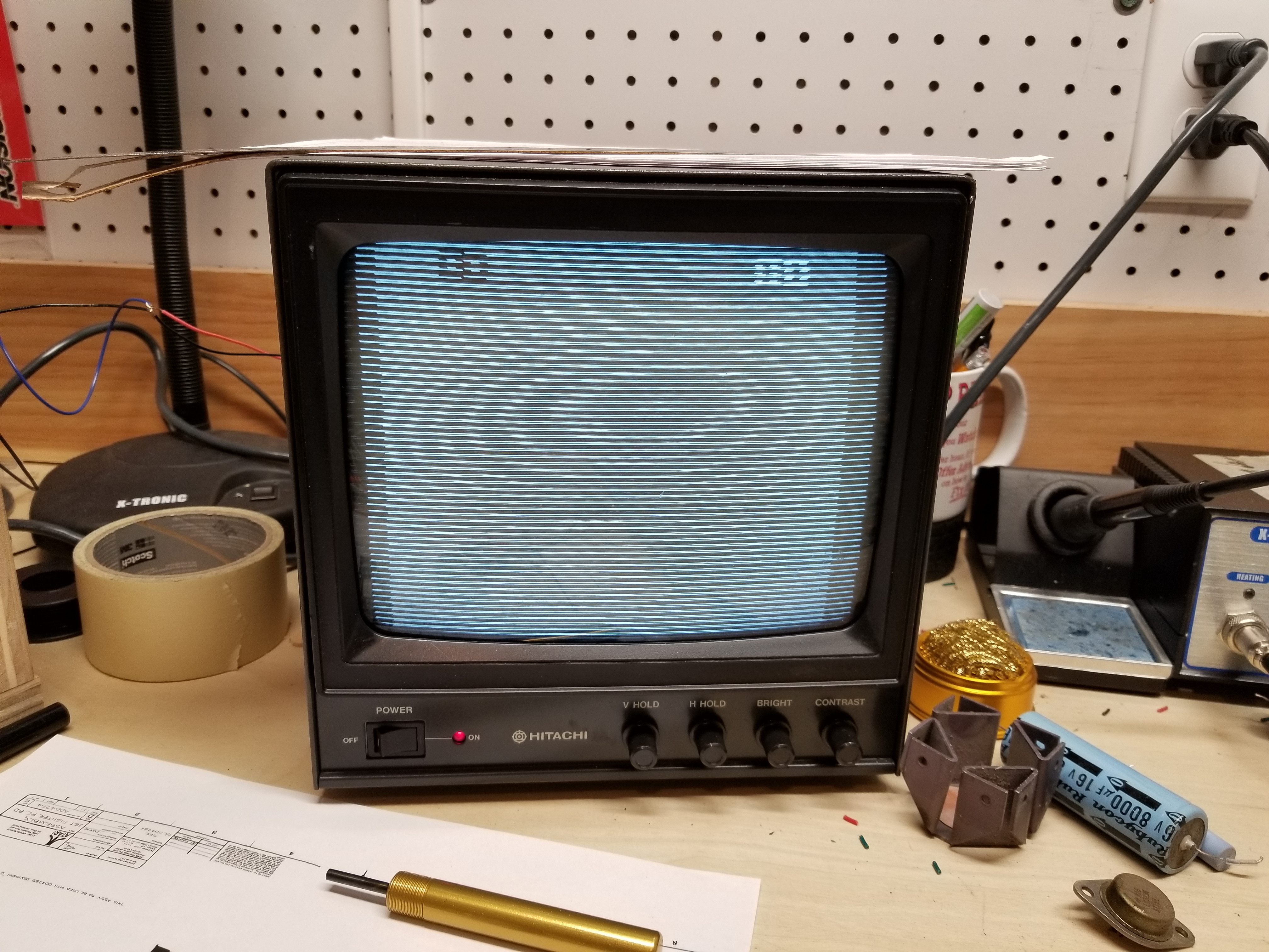
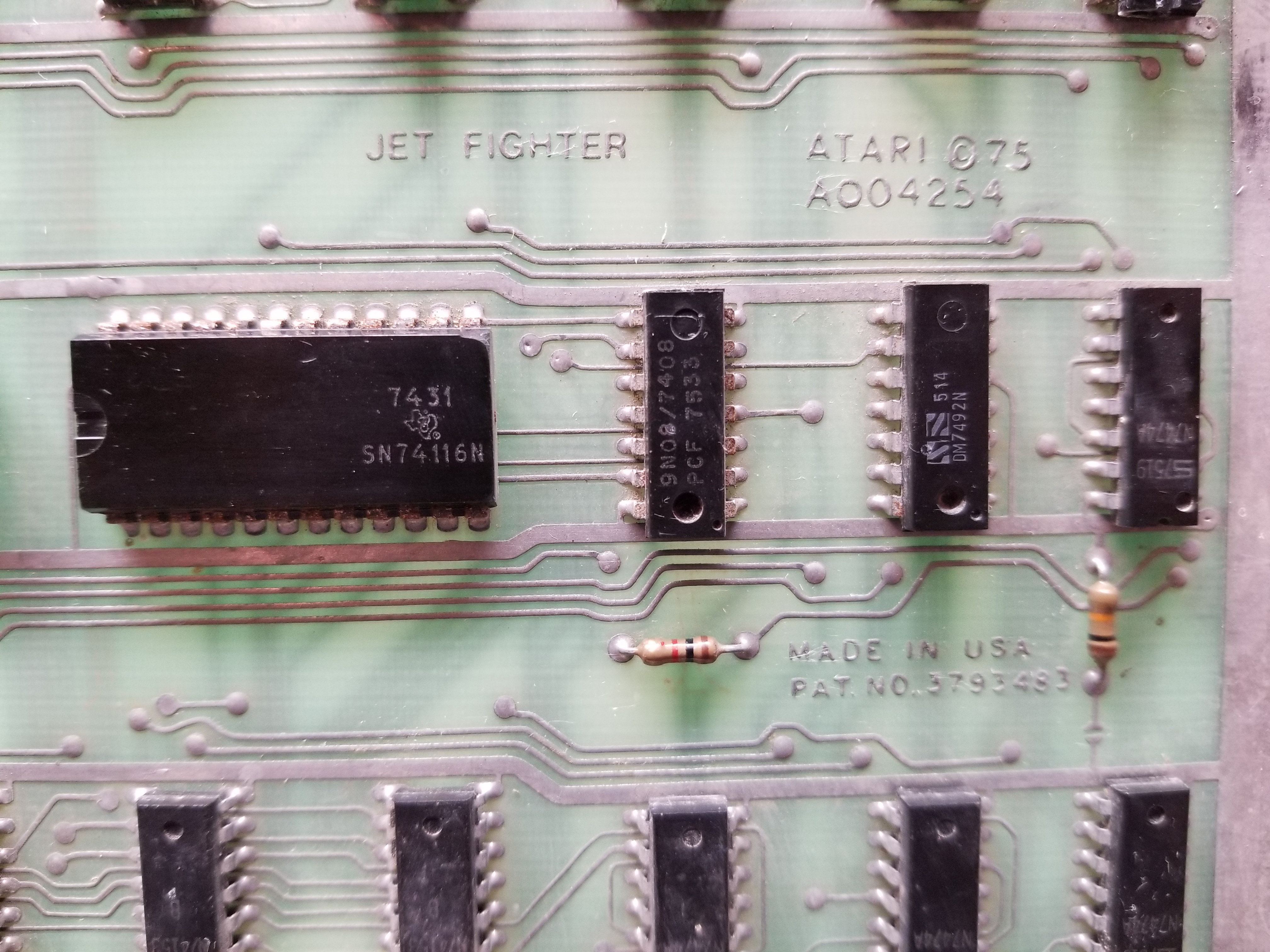
Top: The screen of the fixed game. Bottom: The board right after being taken out of the shipping box.
This is the story of how I fixed an Atari Jet Fighter arcade PCB; the first board I have fixed in over two and a half years. In the interim, I designed the PERISCOPE arcade game with only TTL logic, designed and built the Golden Spike Pinball machine, and began to design the Kincaid Arcade Vector Graphics Card. As a result of all of the things I have learned, I knew much more of what I was doing with Jet Fighter than I did when fixing my other games.
After fixing Atari's Anti-Aircraft, I began to search for my next acquisition on Ebay. After being outbid on several Atari Breakout boards over the years, I decided that perhaps I didn't need to add any new games to my collection for awhile. For several years, I just watched Ebay listings to see what came up and what its price was, and got a feel for the actual "value" of this kind of stuff. One day, a Canadian seller listed this particular Jet Fighter board. At $70 American for the board and shipping, I decided that it would be fun to get one more game. So I did.
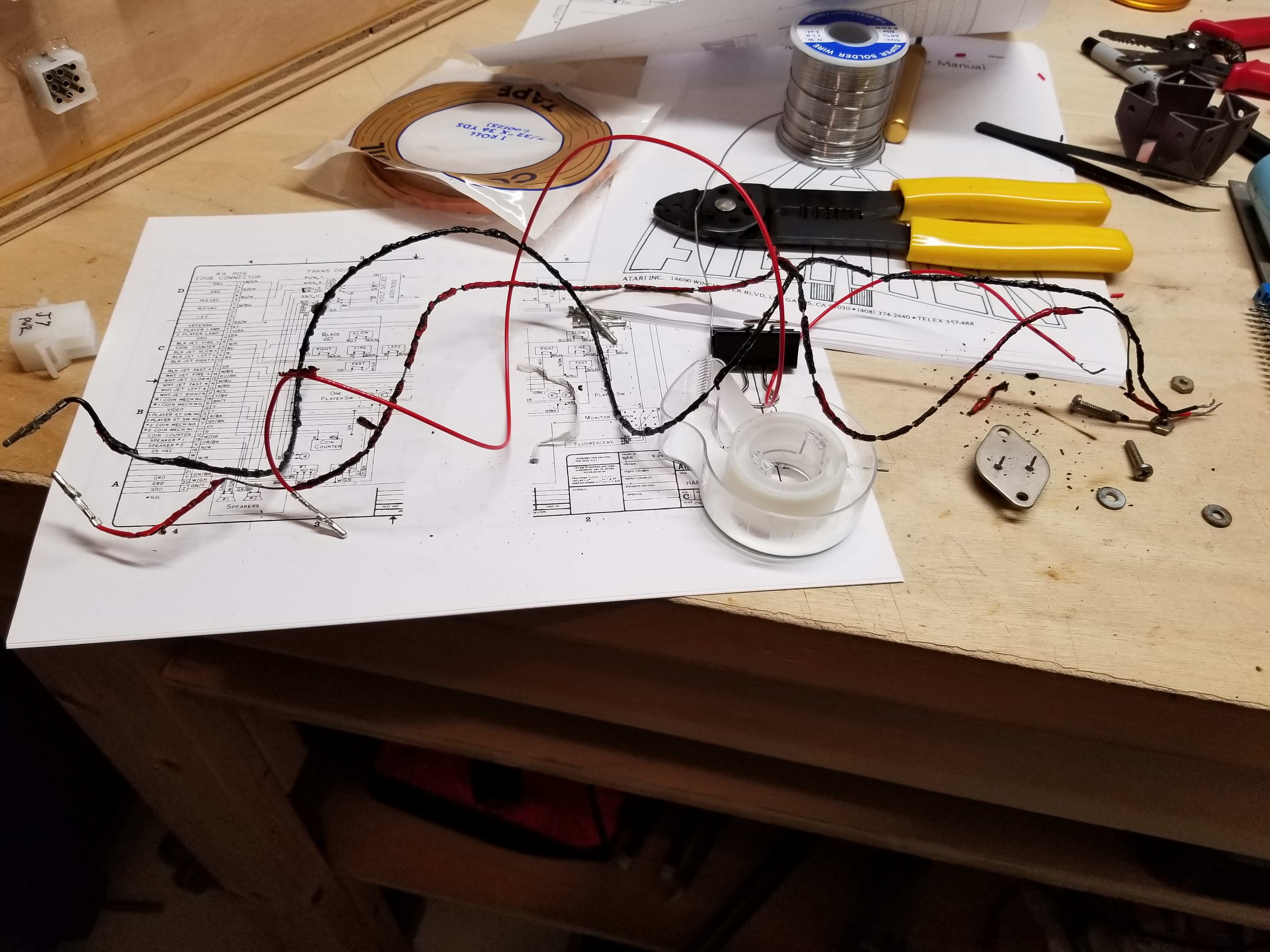
After the board arrived, I was ready to get crackin'. I had even designed and built my own test rig box to keep the amount of wires trailing across my workbench to a minimum.
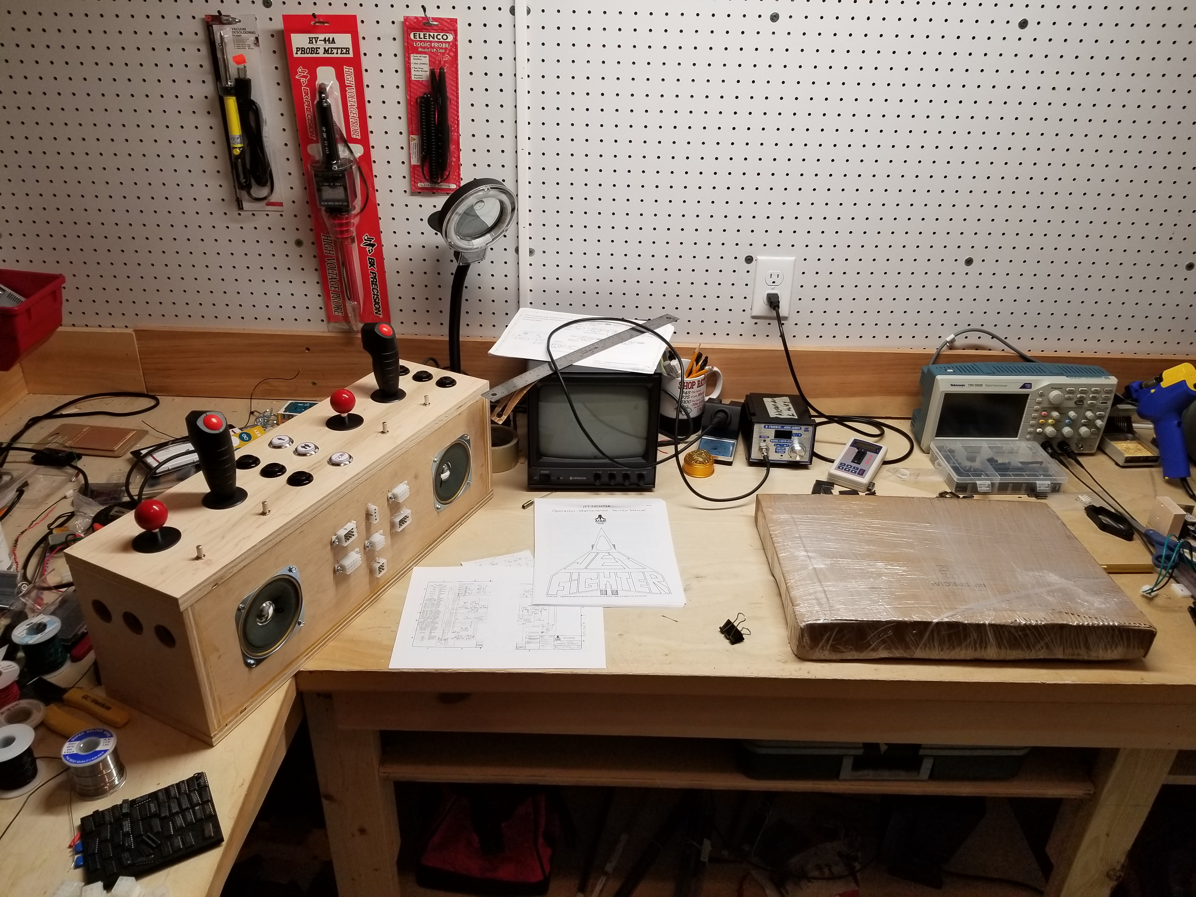
I wasn't messing around when I made this test rig. I loosely based its design around the Kurz-Kasch TF-650. You can read about how I made it here.
After opening the pizza box that the board was shipped in, I was surprised to see just how dirty the board actually was:
.jpg)
Dead bugs, cobwebs, thick dust covering the analog section... this board needed to be cleaned. There were also several particularly large and very dead spiders that I wish I had photographed. :)
Since I was particularly disgusted with the number of dead bugs and the stickiness of the cobwebs, I started by vacuuming all that junk off of the board. To deal with the dust, I got out a toothbrush and a little bit of water and I began to clean everything bit-by-bit.
This is what the board looked like not long after I began cleaning it. Most of the color change is due to moisture on the board, however it did look a little bit better after cleaning it. Being able to read the numbers on some faded chips was a plus.
Before I powered up the board for the first time, I dealt with several issues I saw from giving the board a once-over. The first of such issues was that there was an empty socket at c8. From looking at the manual, I was able to determine that a 7474 was supposed to go there. The crystal was also missing (surprise surprise). I wonder why the crystals are always missing on these boards...
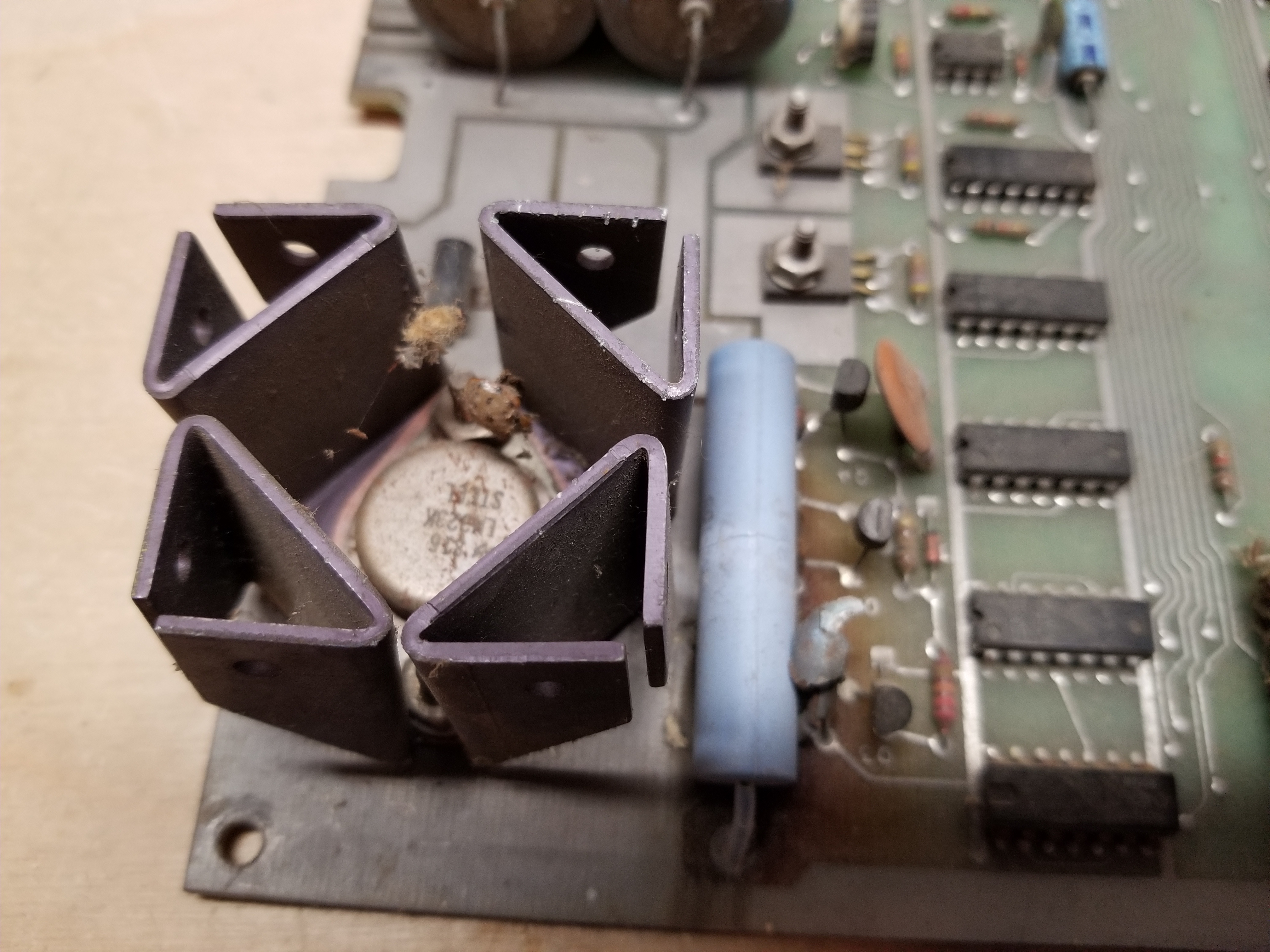
There was another issue I saw that I found a bit concerning. One of the ceramic capacitors in the coin circuit had apparently either caught fire, or had been significantly scorched by the wirewound bypass resistor at some point in its life:
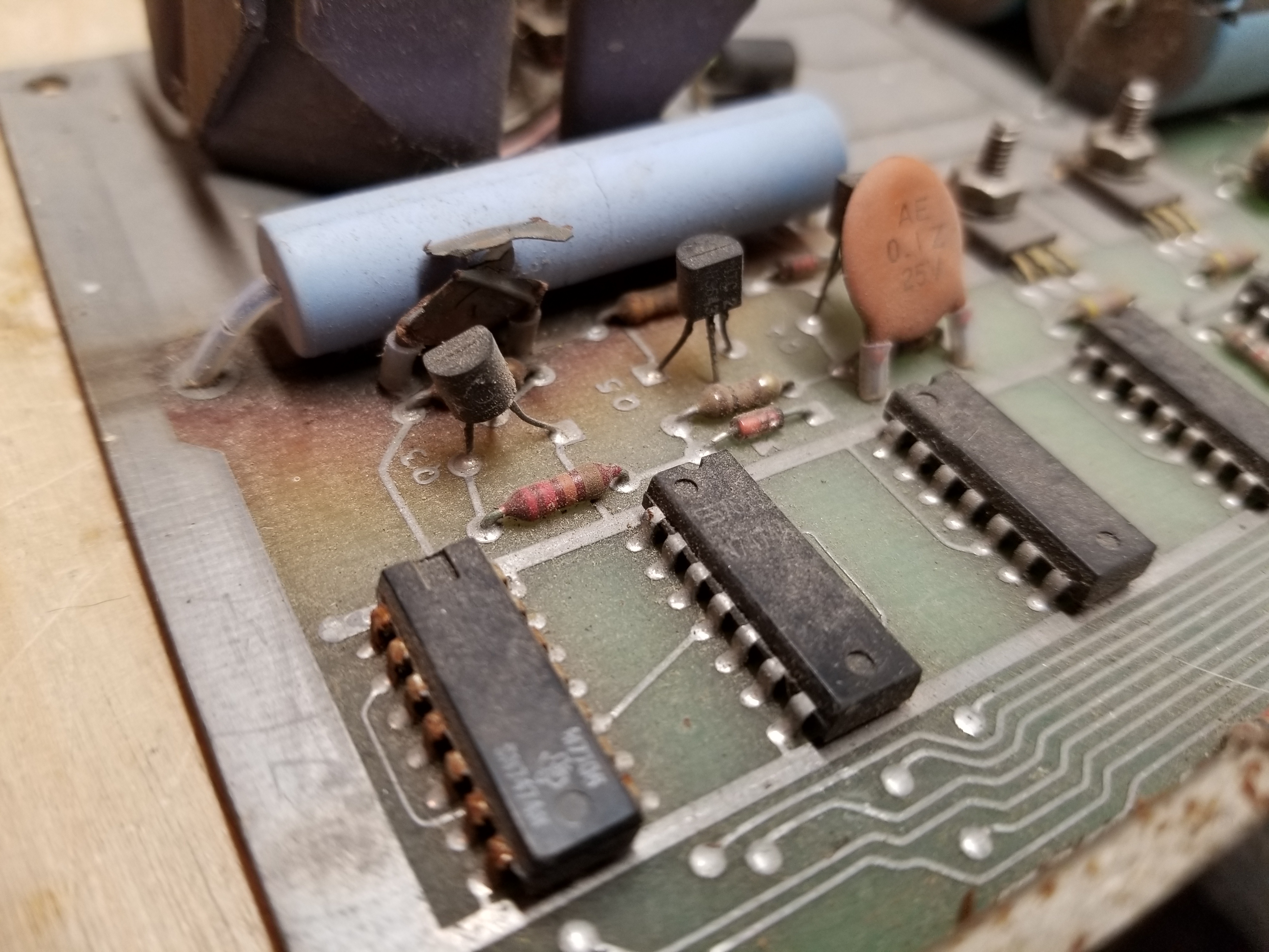
A scorched component is concerning because a failure like that could have also taken out several other components with it. In the case of one of my Olympic Tennis boards, it was an indication that the LM309 failed by shorting the +5 volt line to the 16 volt AC input. That is why everything on that board was fried. Fortunately, that wasn't the case with this board.
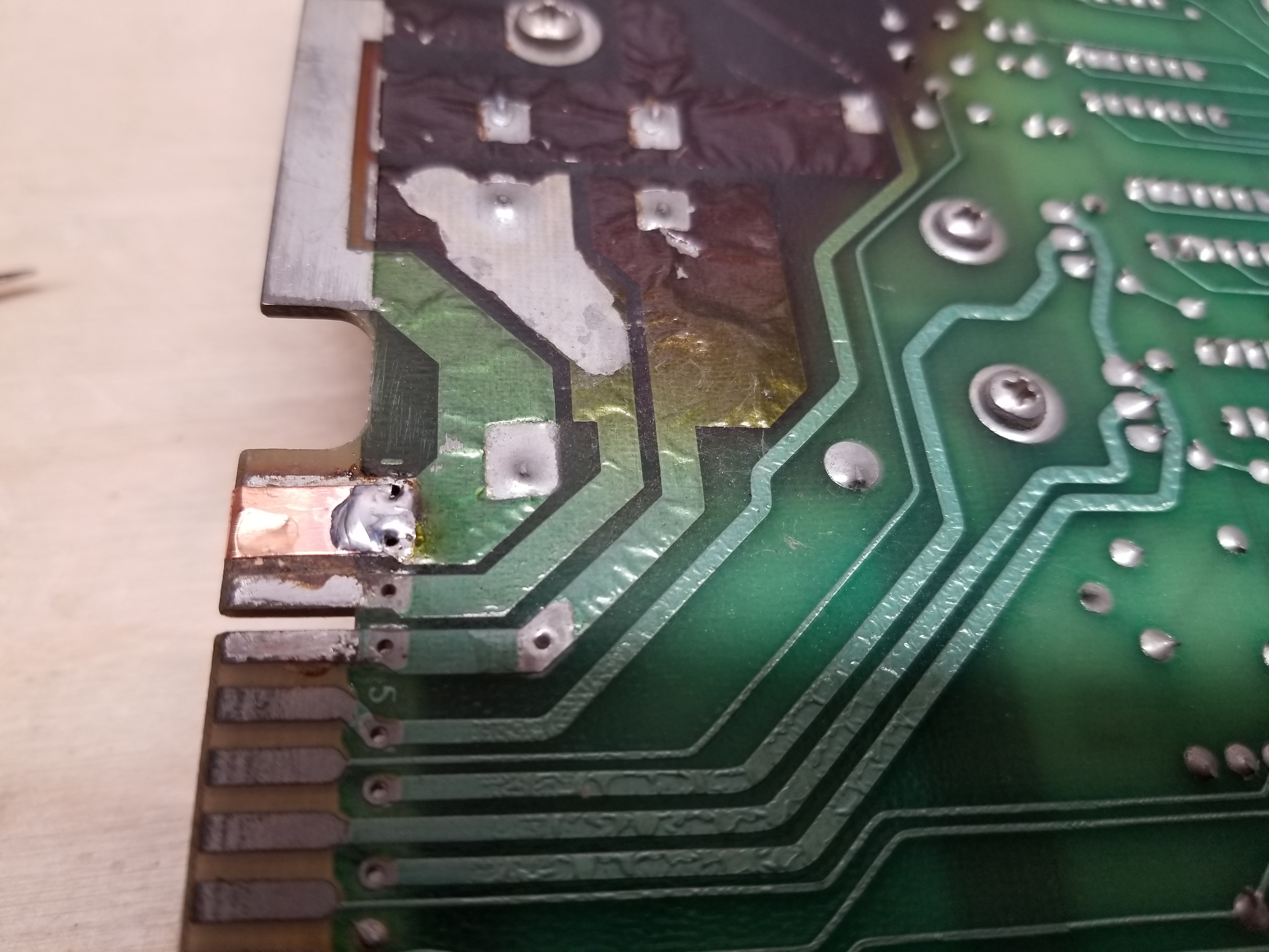
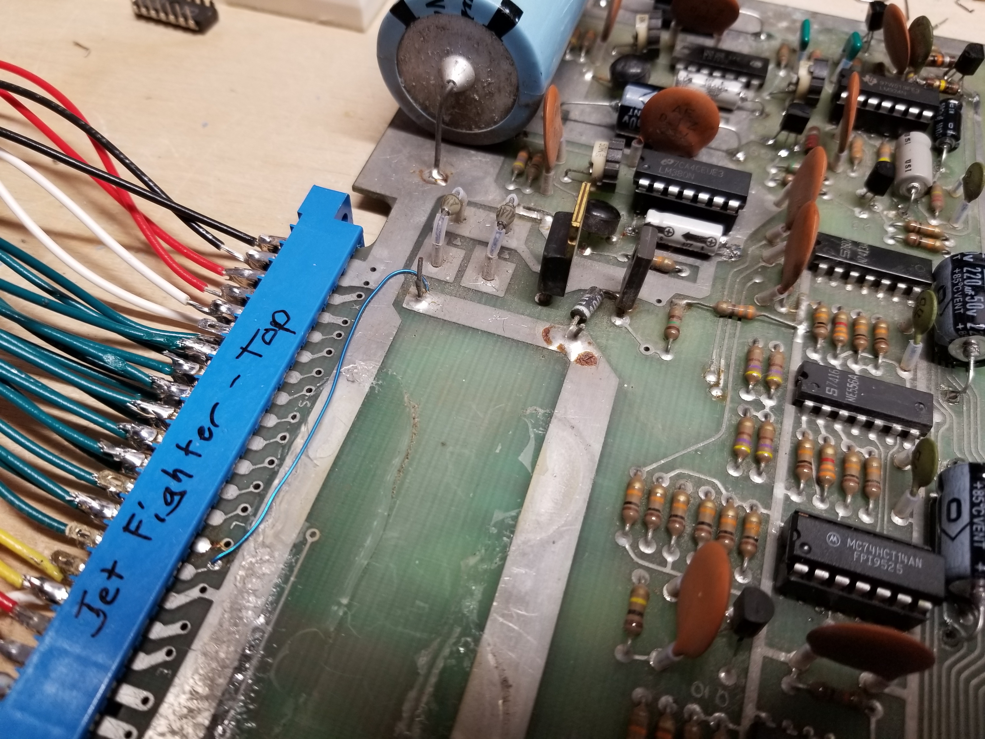
Lastly, one of the ground traces on the edge connector had heated up and had partially flaked off. Apparently the operator had tried to fix that in the past by soldering a component's lead over the spot.
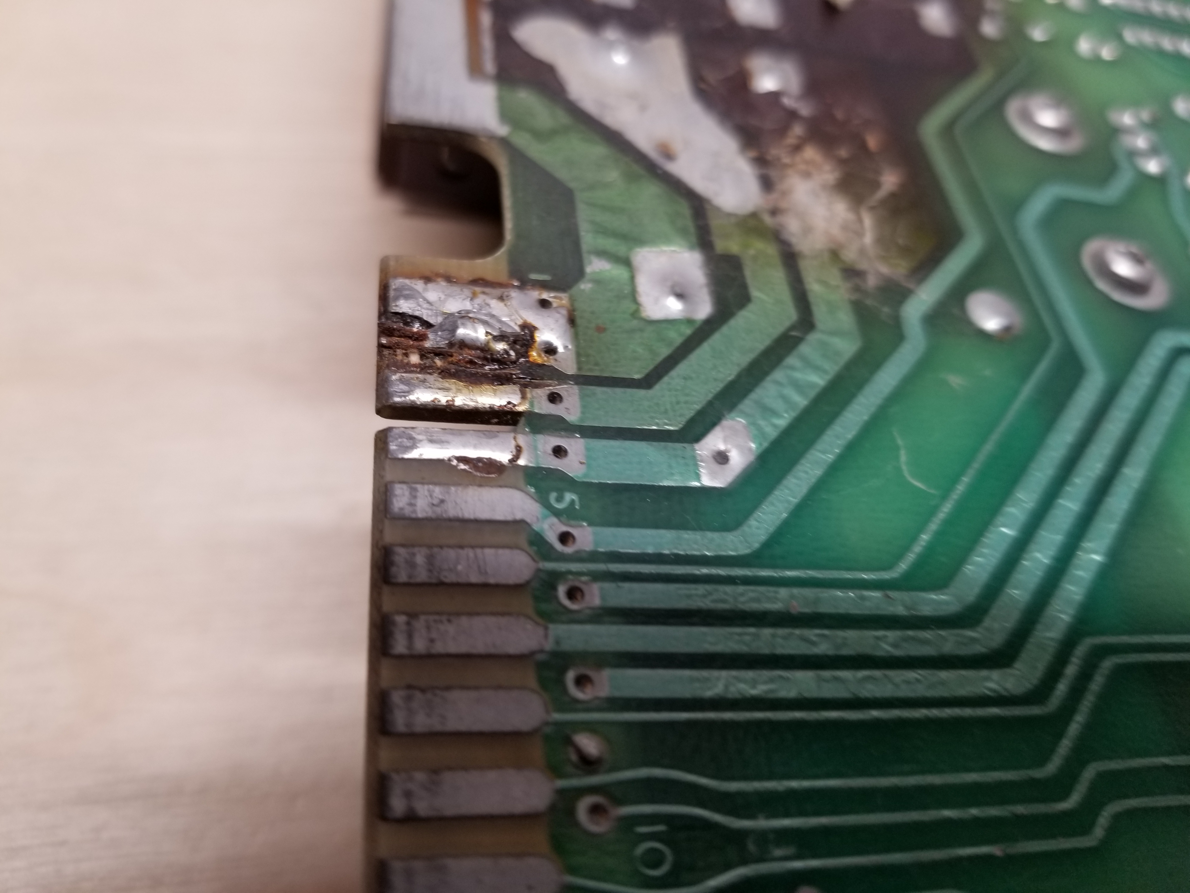
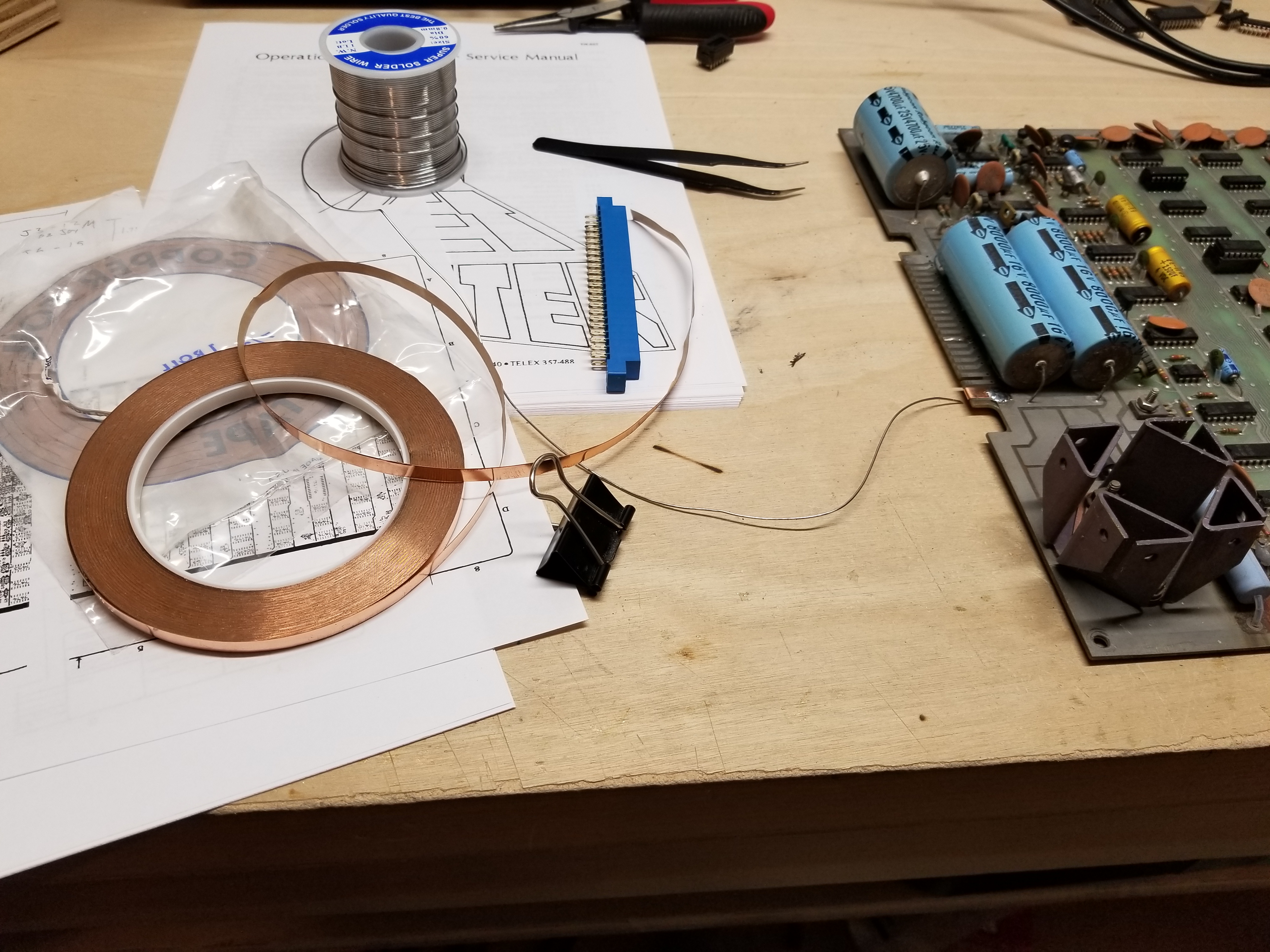
This fix was actually quite thick, which made me wonder how the operator ever managed to get the edge connector over that spot. I know I certainly couldn't. I had seen other people on the internet fix this kind of thing by wrapping it with copper tape and soldering it to the trace. Fortunately, my mom had been into stained glass awhile back, so she gave me some of the copper tape she used for that. Thanks, Mom!
Next came the fun part: soldering up a wiring harness to connect to my test rig box. Normally something like this would be pretty mundane, but I gave myself a bit of a scare when I wired up the 16 volts AC to the board wrong. I accidentally got shifted over by one position when I was wiring things up and, you know, that went well:
I was probing around with my multimeter and trying to figure out why everything was at 0 volts. Then I looked up and saw this -- the wires had gotten so hot that the insulation was boiling.
Fortunately, nothing was damaged. I soldered new wires for both of the AC voltages and everything was working fine. I proceeded with wiring up the test rig adapter, which looked like this:
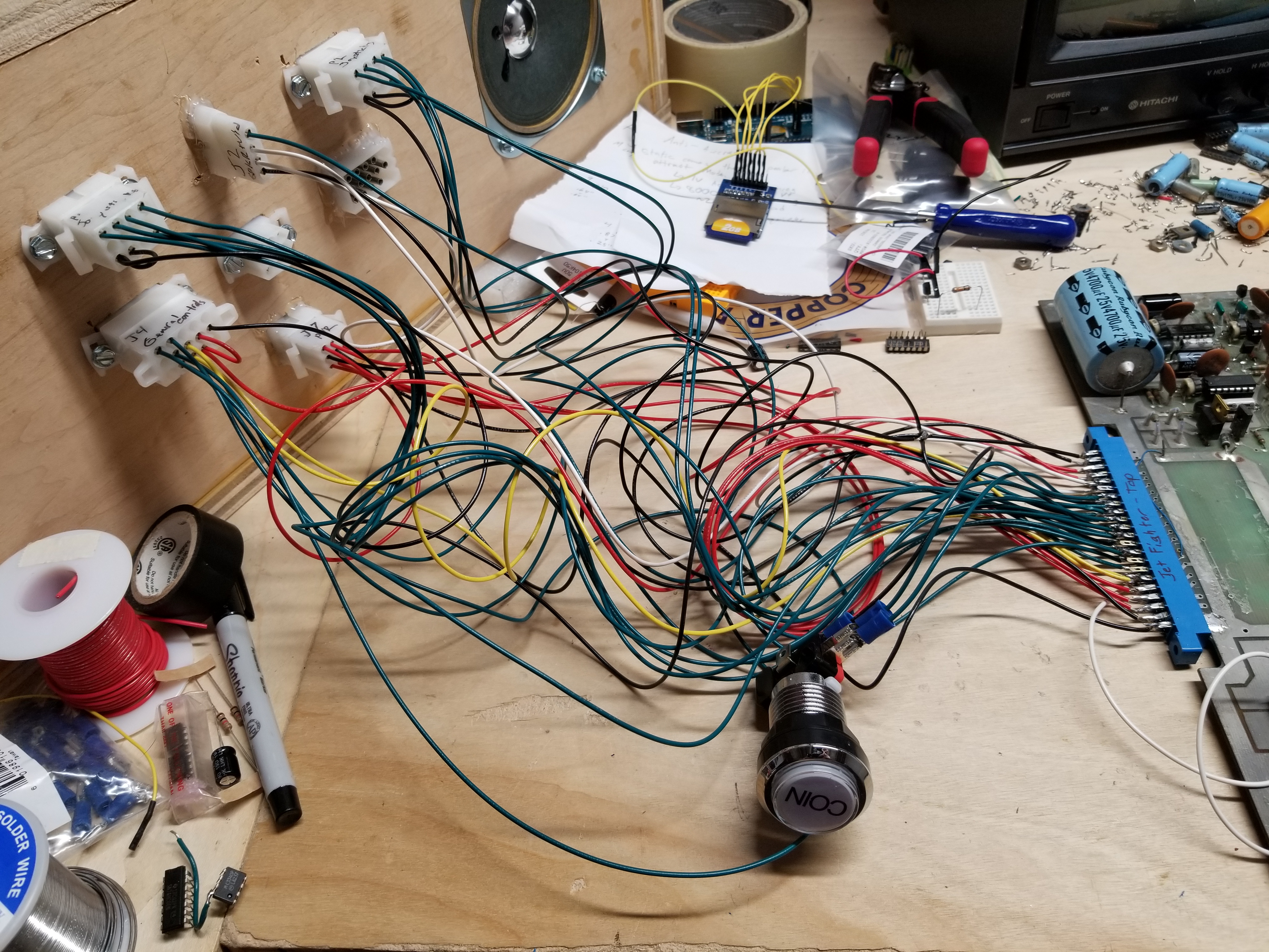
I had to add an extra coin button because Jet Fighter has two independant ones, instead of two that connect to the same circuitry, like on Anti-Aircraft.
With the test rig all hooked up, it was time to power on the board for the first time:
No suprises here; everyone knows "untested" means "not working".
I pulled out my oscilloscope and began to start probing around the board. I started by checking around the vertical sync generators, since the signal 2V was obviously shorted with something in order for the screen to look like that. I didn't find anything, so I began to try and figure out why the jets were missing. According to the circuit descriptions in the Jet Fighter Manual, the white jet was Jet 2, and the black jet was Jet 1. I somehow managed to get this mixed up in my head later on.
While I was looking around the circuitry that sums up the video, I found that the video signals for the black jet (/Jet1 and /Shell1) were floating at F3, which mixes the signals into the White, Black, and Gray outputs. However, checking the sources of those two signals at F2 and E2 revealed that they were there. Since I was fixing a Revision B circuit board with a Revision D manual, I thought it would be prudent to check and make sure that those signals were connected to that chip on my board. I turned it off and did a continuity test with my multimeter, and sure enough, they were connected. I replaced F3 and was greeted with the garbled video of the black jet.
Next, I began to look around the circuits for the white Jet. I got Jet1 and Jet2 switched in my head and started looking at the wrong part of the schematic, which led me back to the circuits for the black jet. I discovered that the output of pin 8 on L5 was floating, which was keeping the horizontal counters of the black jet from being preset, which is how the jet "moves". Replacing the chip fixed the issue, but it wasn't enough to allow the jet to start moving around the screen just yet.
After this, I continued to probe around for awhile, but with no luck. I played the game a couple of times on DICE, and noticed that both of the jets started at the exact same spot when power is applied to the board (something that only happens in DICE), producing an almost unnoticable gray area where the jets are. Starting a game resets both of the jets' positions, allowing them to be seen. I figured that if I fixed the white jet, I wouldn't see either jet for the above reasons. So, I began to work on the coin circuit.
After probing around, I discovered that the COIN signal was floating. I replaced the 7404 at C7 and the COIN signal could toggle again. The game still could not be started. The 2 Credit signal worked, but not the 1 Credit. I checked D8 against a truth table, and sure enough, pin 6 was stuck low, regardless of what the two inputs were. I replaced it with a 7400 and the credit signal worked, but I still could not start a game.
I had no idea what could be wrong, so I figured it had to be one of the transistors in the coin circuit, since that had been the problem in both QWAK! and Olympic Tennis. I replaced Q3-Q5, but that still did not fix the issue.
I was stuck on this issue for a long time. I always wondered what the "Q" signal was used for, so I read the circuit description in the Jet Fighter manual. It is a circuit that rejects the coin drop signal if the antenna detects static. The "Q" signal is really just the coin signal, but "authenticated". If the coin is not authenticated, a 0 is clocked into the 7474 at C8, and there is no change. After all these years, I finally understood how this type of circuit should work! But what caught my eye was where it said "The latch is set via diode d6 when the /coin signal goes low..." (pg. 20). But that was not happening. I replaced D6, but that didn't fix the issue. I looked at F8. Huh. It's been replaced before. I yanked it out of the socket and put it in my chip tester. It was bad. The socket was rusted so I replaced that as well. Finally, I can coin up the game and start it.
Here is a video of what the board was doing after I fixed the coin circuit:
So I can coin up the game now. But I still can't play because the white jet is missing. So, I began to look at the signals for the white jet.
Probing around the signals for the white jet revealed that the motion circuits were working, however the output from the shift registers that load the plane data was dead, so I took a look at that circuit. The issue was because the strobe (enable) inputs of the '165s at F4 and K4 were floating. I replaced the 7400 at D4 and the white plane was present again.
Yay. The black jet is now AWOL again.
In trying to fix the circuits for the black jet, I began to suspect that the final gate that sums everything together into the signal for the black jet wasn't working. I compared it to a truth table and thought it was bad, however, replacing E2 did nothing.
It was about this time that I noticed that every PROM on the board was very, very, hot. Almost hot enough to burn my fingers when I touched them. I checked the board voltage; it was fine. The problem was that every single input pin was floating. The problem was with K2, a 9322. I replaced it with a 74157 and the PROMs didn't heat up as much. It should be noted that they still do run fairly warm in normal operation, though.
Next I took a look at the 82S25s; some of the other chips that were heating up. All of their inputs were floating. All the outputs of the gates at P8 (7400) were floating and only one gate was still functional at L8 (7404). I replaced them, and the 82S25s don't run hot anymore.
Now that my concerns about the PROMs cooking themselves to death were nonexistant, I began to try and figure out why the black jet was missing. Like the white jet, the issue ultimately was with the shift registers that load the plane graphics. Both the output pins on H4 (a 74165) were stuck high. Something like that is a telltale sign of a problem since one output is the inverted form of the other. I replaced it, and the black jet appeared again.
The planes don't fly correctly and have corrupted graphics. Well, it's progress.
The black jet is there, it is just very hard to see.
I began to take a look around the jet motion circuits again, and found that one of the gates that determines how many counts are skipped or added was floating. I replaced M7 (7404) and took the following video:
If you look closely at the video, you'll notice that on some of the rotations of the plane, the jet image is correct. On others, it is not. "Oh, no." I thought to myself. "One of the plane PROMs is dead". Sure enough, I tested and found that one of the "Jet and SC PROMs" (J5 & K5) had all of its outputs floating. Great. Now I need to figure out some way to replace the PROM. I remembered that hobbyroms.com could program Bipolar PROMs. $25 PER CHIP! There has to be a cheaper way to do this. Since Jet Fighter had room on the board for a larger ROM at F5 to replace K5 and J5 if that was the type of chip that was availible, I figured I could make some kind of adapter for a 2732 or whatnot.
(It is possible to use a slower ROM like this because Jet Fighter loads the data for the planes into a shift register, since even a 150ns PROM is too slow to race the beam. Given the length of the load pulses, it is quite probable you could use a 450ns EPROM, if you so choose.)
The ROM folder for Jet Fighter in DICE unfortunately did not have the dump for the larger chip. That meant I would have to stitch together the top and bottom 4 bits of the K5 and J5 dumps to get the data for the F5 chip. I did not immediately know how to do that, so I went back downstairs and miserably stared at my board for while. I pulled the defective chip off the board and glumly thought about how difficult it would be to fix. I put it back in and fired up the board. THE CHIP WAS WORKING!!!
As it turned out, the socket the chip was in was all rusty, so the pins weren't making good contact. I replaced the sockets, and the plane graphics were correct.
However, having the planes display the correct graphics isn't very useful if horizontal lines are alternating everywhere on the screen. Previously, I had thought that the signal 2V must have been shorted to something for the screen to look like that. Since I didn't see anything before, I decided to compare all of the synchronization signals with their drawings in the manual. As it turned out, the VSYNC signal was shorted to 2V. I replaced the 7474 at B6, and finally, the screen looks right:
The fix for the computer-controlled jet spinning out would be discovered later.
"Spinning out in circles, in circles, in circles..." - Switchfoot
The next problem I worked on was the ability to fire the bullets. The bullet circuit for the black jet was particularly troublesome.
The first problem that I found was that the bullet was being held in the "reset" state by a floating output on E5 (7410). Firing up the game after replacing E5 made the explosion/fire sound happen repeatedly. Since I didn't want to have to constantly listen to the explosion sound while trying to fix the issue, I tracked down why the jet was always firing. The Fire Com 1 output of multiplexer J8 would float when it tried to go high. J8 switches between the joystick controls and the computer controls. Replacing it with a 74157 fixed the firing issue, as well as the plane spinning out.
Unfortunately, the bullet for the white jet was also being constantly fired, and fixing that required a chip I didn't have. I had to listen to the explosion sound anyway. :/
I still had not yet fixed enough for the black jet's bullet to appear on the screen. I checked the horizontal and vertical windows, and they were good. I found that the output pin (14) of the 9312 at H1 was floating. Replacing this allowed the graphics from the PROM at J1 to be drawn on the screen:
I did not fix the other issues with the black bullet since I thought I had tracked that down to a chip I did not have. More on that later...
So, I began to work on the white bullet. The first issue I found was that the horizontal counting chain wasn't counting. After checking that all of the conditions were right for the chip to count, I determined that the ripple carry output (pin 15) of the 9316 (74161) at H2 was bad. Replacing it revealed this undefeatable wall of fire and glory:
In order to fix the vertical bar, I had to replace two chips with the exact same issue as above. Replacing J2 made the bullet a dotted line (I wish I had taken a picture) and replacing K2 made it fire normally. Well, it was stuck firing, but I was waiting on a part for that...
After playing the game for a bit in this state, I noticed that the score for the white jet didn't count linearly. Probing the counter at B5 revealed the counter was working properly. Probing the multiplexor that feeds the score to the score pixel PROM revealed that the (zero-indexed) 3rd bit (0 1 2 3) was stuck low. I replaced A5 with a 74157 and the score was fully working.
The last issue I had while waiting on my parts order was that the game never ended. According to the manual, the 555 timer at k9 forms a voltage controlled oscillator, which after outputting 8 pulses, ends the game. Checking pin 3 on my oscilloscope revealed it wasn't outputting any pulses. Replacing it fixed the game timer.
At this point, I had tracked down several other issues, but did not have the chips on hand to fix them. I placed a parts order for the chips and some capacitors to recap the board.
When the parts order arrived, I was able to get the digital portion of the game fully working.
The white jet had always been firing because pin 4 of the schmitt trigger inverter at H9 (7414) was stuck high, making it look like the button was being held down.
The black jet would only turn left, and only in the cardinal directions, because the two LSBs of the up/down rotation counter at H6 (74193) were stuck low, as well as an issue with the up/down pin.
Lastly, the bullet of the black jet was flying way too fast vertically. Originally, I suspected the 74116 latch at L3/M3, however, checking again before replacing the chip led me to believe it was working. I checked, and it was doing the same thing as the other one. That left nothing else in the circuit I knew for sure wasn't working. So, I made an educated guess. If the bullet was moving at the wrong speed, the counters weren't being preset correctly. Since the presets weren't being used on L2, and it had already been replaced, that left M2 (74161). I replaced M2 and the bullet moved correctly. At this point, the game was now fully working, except for the sound. I had recapped the audio section of the board, and replaced several other components. I suspect that the noise circuit isn't working properly, but I've not been able to figure out why.
I know that the "noise selected xistor" as the manual calls it, is just a 2n3643, but I replaced it and it didn't fix anything. The op amp was replaced, too. The Noise output is dead. I have replaced all of the transistors. If anybody has any useful information, please, email me!
At any rate, the game plays, and sounds almost as good as the sounds in blinddog44's gameplay video.
Gameplay Videos
Single Player:
Two Players:
What is a "Noise-Selected Transistor?"
I've been trying to fix the sound on my Jet Fighter and QWAK! boards, but I have been unable to figure out why there is no white noise output. I'm not joking when I said that I've shotgunned and tested every discrete component in each circuit, and they still don't work. How could that possibly be? Well, The Secret Life of Synthesizers did an article that happened to explain why. Everything to follow are the key takeaways of that article:
- Manufacuting processes weren't too good in the '70s and '80s, so there were a lot of components that were rejected due to being out of spec.
- Some of these out of spec components had desirable qualities, such as the noise they generate when they amplify something.
- Some manufacturers found these qualities extremely desirable and unique, and designed parts of their products around them.
- Replacing a "Noise-Selected Transistor" with it's associated part number won't work, because their electrical characteristics are different.
What this means is that replacing the noise selected transistor on Jet Fighter or any other game with the "exact part number" will make the circuit not work. The transistors with the same part number generate almost no noise whatsoever, which is why the manufacturers had to use rejected parts. What ever you do, DO NOT REPLACE THE NOISE-SELECTED TRANSISTOR, except with a verified noise-selected transistor!!!
Revision-B Jet Fighter Factory Modifcations
This list was compiled to the best of my ability. It is likely missing mods if traces were cut that are underneath any chips.
I hope this helps in lieu of there being no REV-B manual on the internet!
- Connect a jumper wire from +7.5 VDC unregulated to pin J on the card edge connector.
- Connect a 1N4001 diode (D9) with the banded side on +7.5 VDC unregulated and the other side on the collector of Q11 (2N5190)
- Connect a 330 ohm resistor between +5 volts and the pin of resistor R43 (150 ohm) closest to the ground trace/pour.
- Bend the emitters of Q1 and Q2 and solder them to the ground trace.
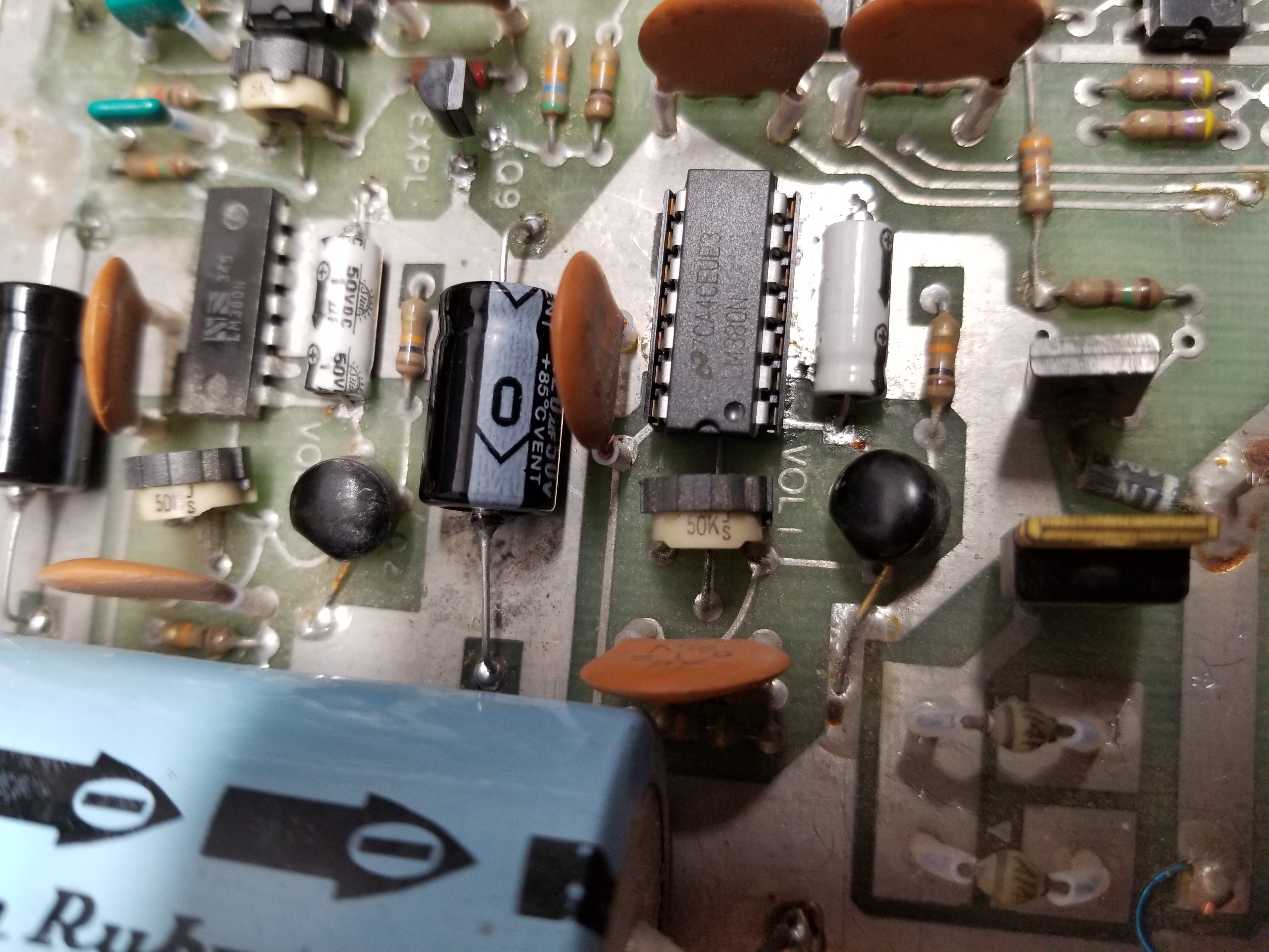
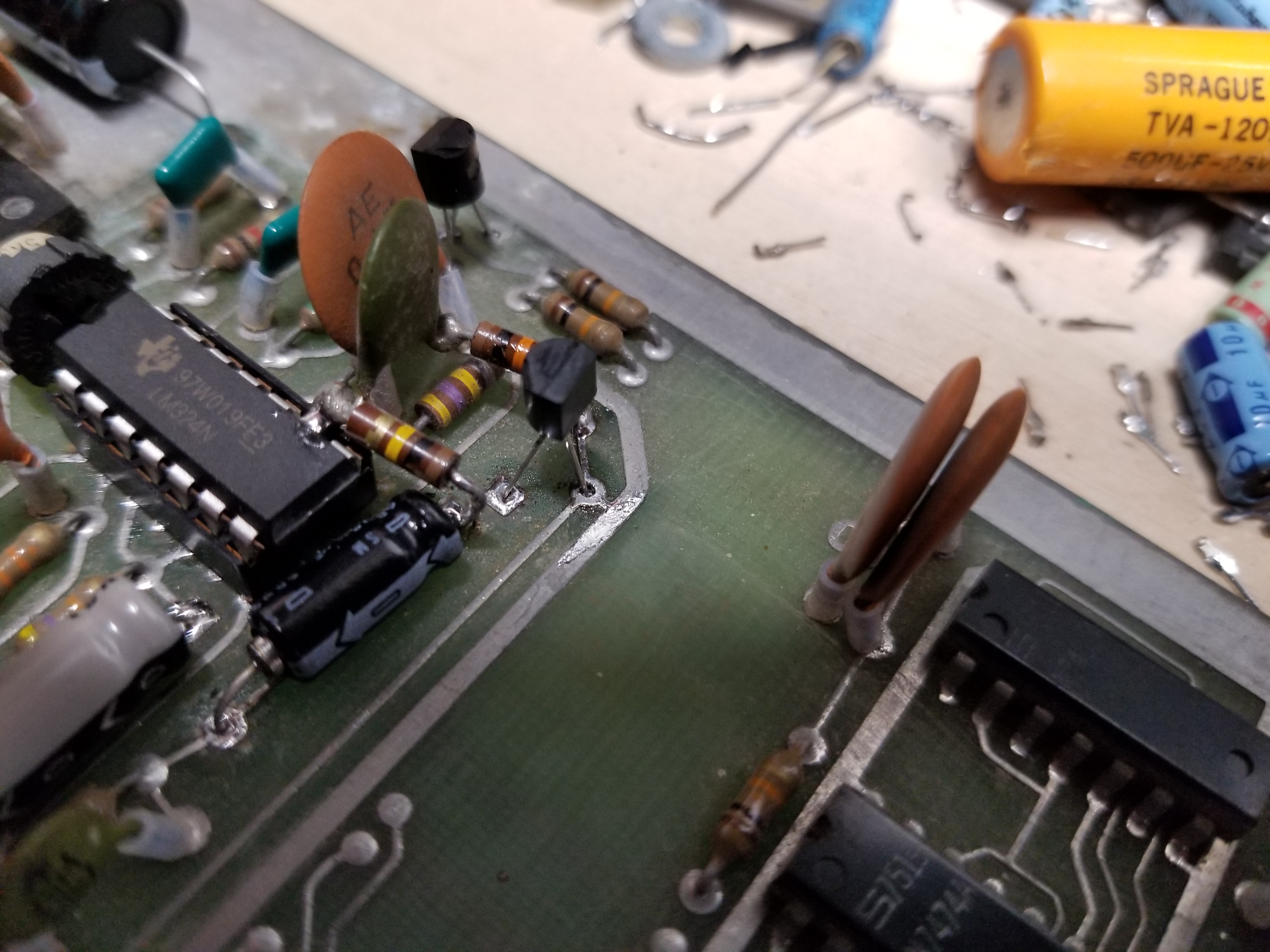
- Connect a 100K resistor between pins 8 and 9 of the LM324 op amp. (That leg of the capacitor works too)
- Connect a 10K resistor and a .1 µf capacitor in series between pin 9 of the LM324 and the collector of Q6.
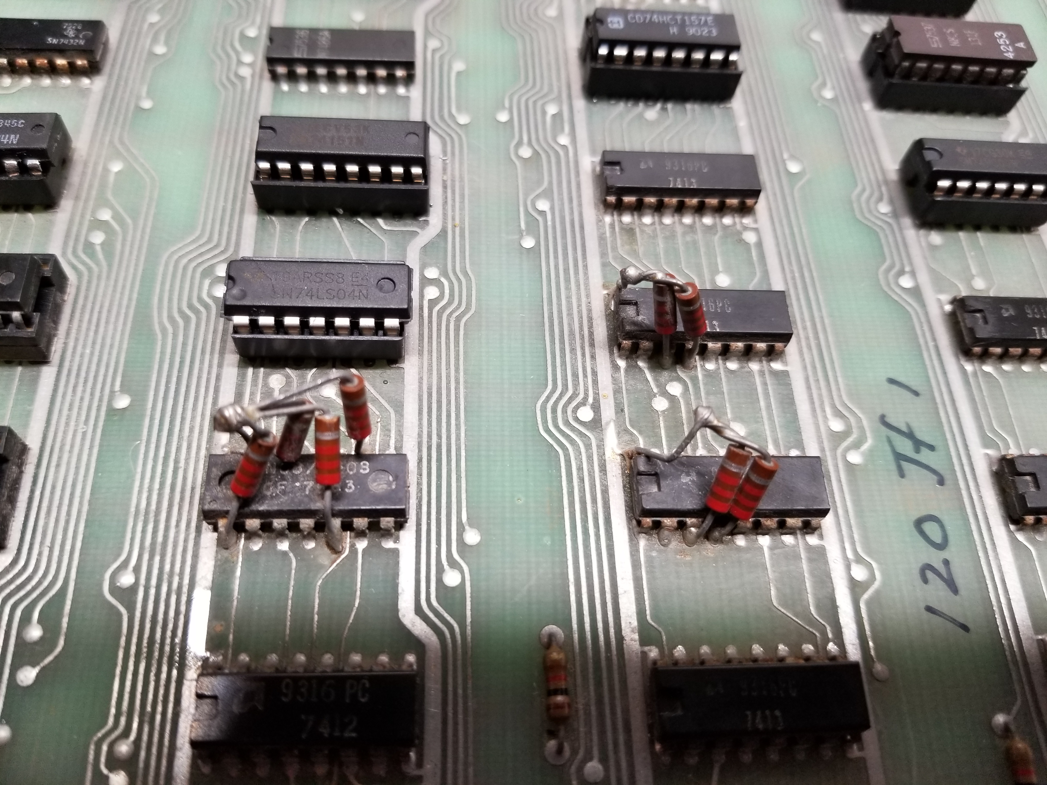
- Connect a 2.2K pullup resistor to pins 3 and 4 of the 9316 (74161) at M6.
- Connect a 2.2K pullup resistor to pins 3 and 4 of the 9316 (74161) at N6.
- Connect a 2.2K pullup resistor to pins 1,5,9, and 13 of the 7408 at N7.
Images:
Misc. Info
There are several other things I came across while working on Jet Fighter. Here they are:
- I had originally thought the MC14508BCP (MC4508) was the CMOS equivalent of the 74116. It is not.
- If you do not connect the lamps to ac voltage, but use dc instead, the MCR106's will be able to turn on the lamps, but not turn them off. Use AC voltage!
Misc. Images
Lastly, here are some images that I couldn't find a place for in my write-up:
This page was first published on 8/30/2020
This page was last edited on 1/5/2022
Spelling, grammar, and readability corrections.